Content
As a fall-protection manufacturer and supplier, we work with roofing contractors, steel erectors, and industrial maintenance teams who need one thing from a lanyard system: predictable performance in real travel paths. Rooftops and steel structures are unforgiving because you often have edges, openings, and foot-level anchorage in the same day.
In this article, I’ll explain how we plan lanyard length and travel planning for rooftop & steel structure work—using practical clearance math, anchor layouts, and selection rules you can apply before you purchase or deploy equipment. For reference on configurations we manufacture, you can review our safety lanyard product page.
On a low-slope roof, the critical question is usually, “Can the worker reach the edge or skylight?” On a steel structure, the question shifts to, “Can the worker stay connected while moving between members and anchors?” Lanyard length controls both outcomes, but only if you define the travel path first.
If your site objective is restraint or positioning, “longer” is rarely “better.” The safest rooftop programs often succeed by making the lanyard shorter than the distance to the edge, while steel programs often succeed by designing transfer points so a worker is never forced to unclip.
When you are in fall arrest mode, the “right” lanyard length is the one that fits your available clearance and anchor position. The fastest way to eliminate unsafe options is to calculate required clearance conservatively, then select the connection method that stays inside that limit.
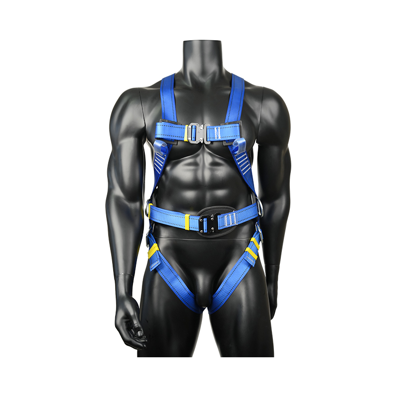
Required clearance = Free-fall distance + Deceleration/elongation + Harness/D-ring shift + Worker allowance + Safety margin
If you are working under U.S. OSHA construction requirements, personal fall arrest systems must be rigged so an employee cannot free fall more than 6 ft (1.8 m), and maximum deceleration distance is limited to 3.5 ft (1.07 m). Those two numbers alone can eliminate many “standard length” assumptions when the anchor is not overhead.
Assume a worker is tied off at foot level on a steel beam and there is a lower level below. Even if the lanyard itself is around 1.8 m long, the system can still require substantial clearance once you add deceleration, harness shift, and worker allowance. In these situations, we often recommend changing the anchoring approach (overhead where possible) or switching to a connection method that reduces free-fall distance, instead of simply choosing a different lanyard length.
If you want to align your selection with your own internal guidance, you may also find it helpful to reference our safety lanyard selection guide, which explains restraint vs positioning vs fall arrest in more detail.
On rooftops, the most effective “lanyard travel planning” is often restraint planning. If you can prevent the worker from reaching the leading edge, you eliminate free fall, reduce rescue complexity, and simplify training.
Restraint check: Anchor setback distance must be greater than the worker’s maximum reachable radius (lanyard length + body reach + any slack).
If the anchor is offset from the work area, a fall can become a pendulum. To reduce swing fall, keep anchors as high and as in-line with the travel path as possible, and avoid working far to the side of the anchor. When roofs have multiple penetrations or equipment corridors, we advise mapping anchor points first, then choosing lanyard length to keep lateral movement inside a defined safe corridor.
Steel structure work introduces two recurring challenges: foot-level anchorage (increasing free fall) and frequent transfers (increasing the risk of being unclipped). The objective is to design the travel path so the worker can stay connected without improvisation.
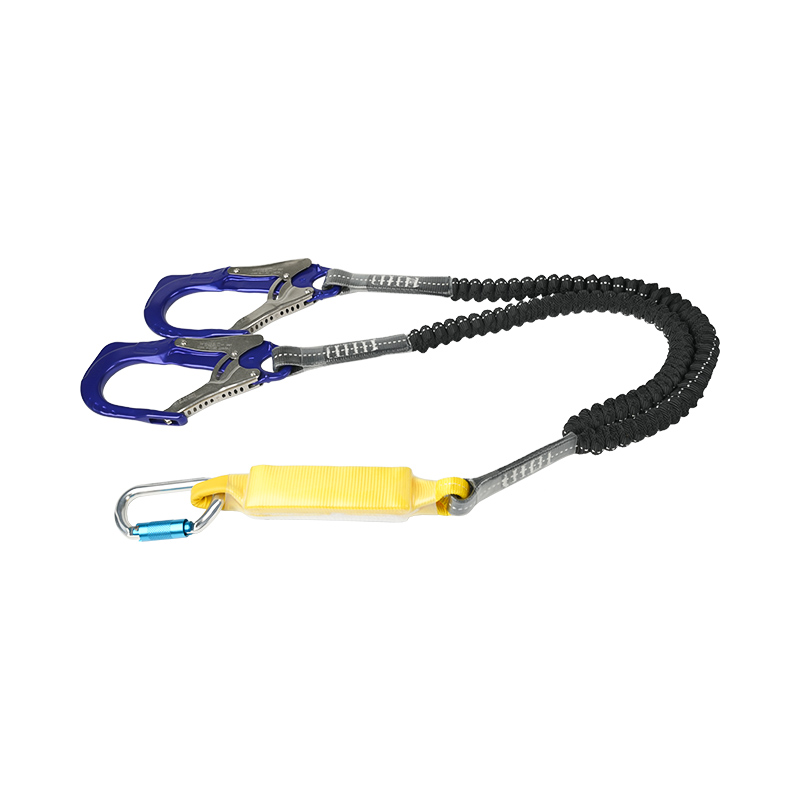
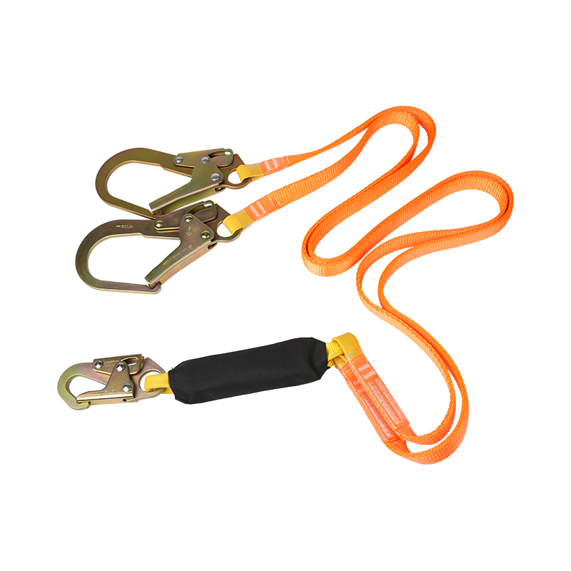
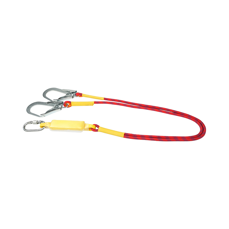
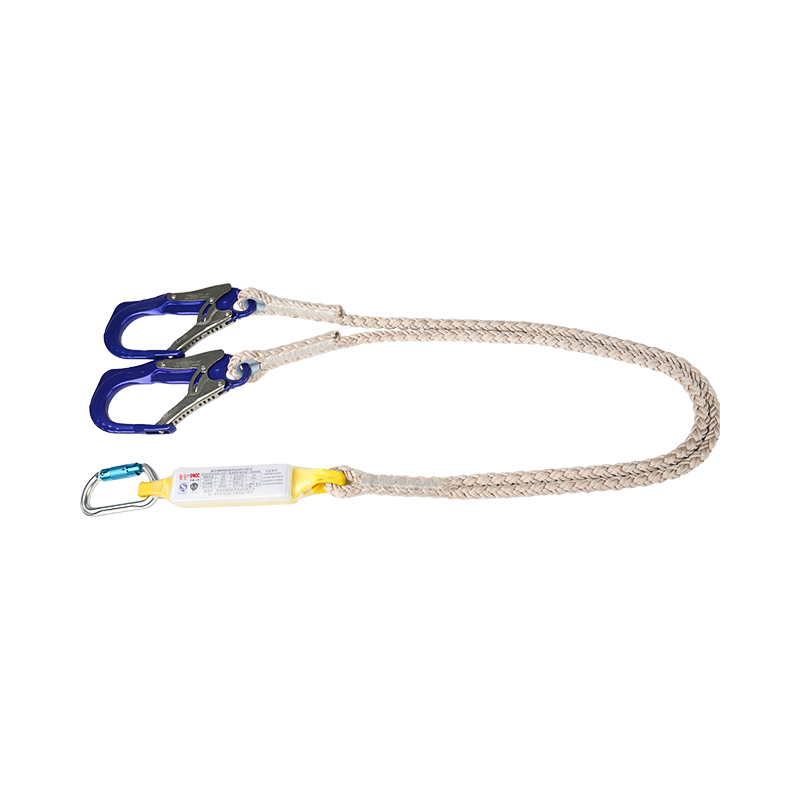
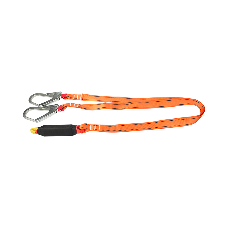
If the job requires repeated moves between anchors—beam-to-beam, ladder-to-structure, or around bracing—twin-leg (Y-type) lanyards can support continuous tie-off during transfers. When buyers ask us what to purchase for transfer-heavy work, we often start with the anchor layout and connector geometry, then confirm whether a twin-leg design is appropriate. For typical configurations, you can review our Double Safety Lanyard page.
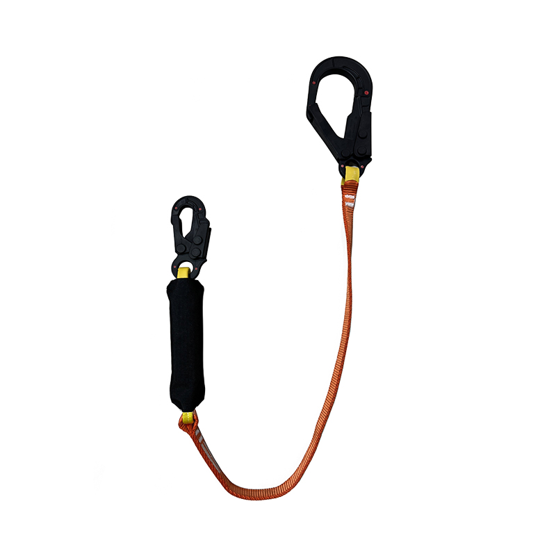
On steel members, the wrong connector can create side-loading, incomplete gate closure, or accidental roll-out. In our product specifications, it is common to see scaffold hook openings around 6 cm and connector strength ratings above 22 kN, because steel work frequently demands robust hardware. The correct choice still depends on the member size, the anchor ring design, and whether the connector can fully seat and lock.
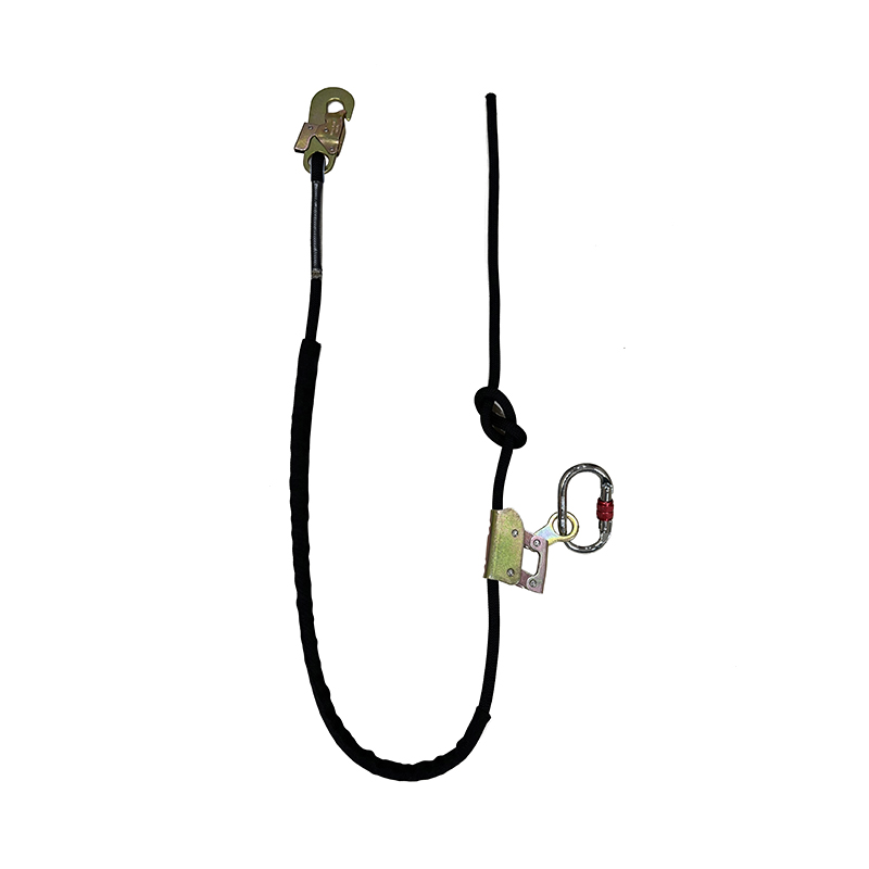
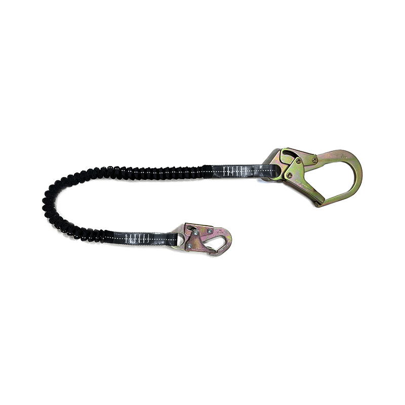
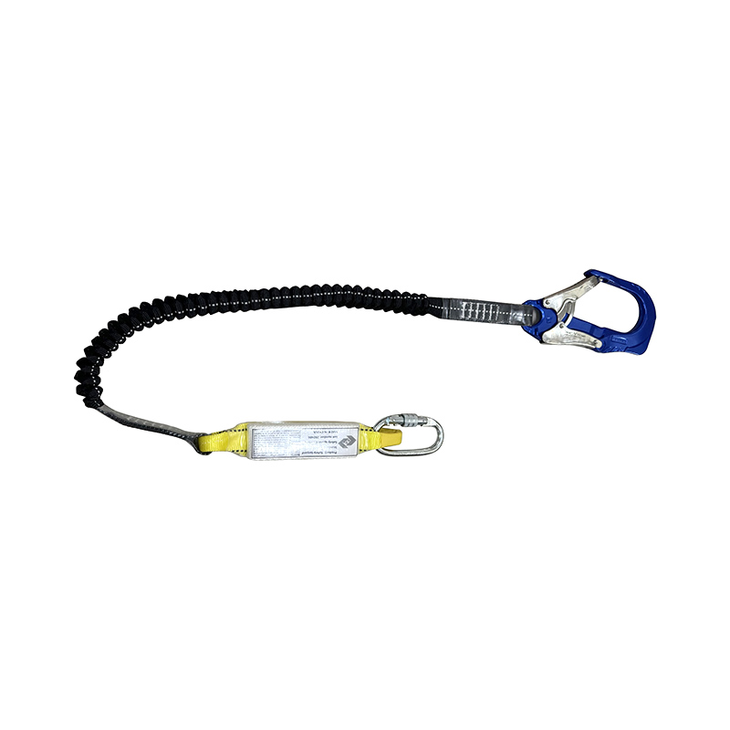
If your work is primarily single-anchor tasks (maintenance at a fixed point), a single-leg configuration can be more manageable and reduce snag risk. For examples, see our Single Safety Lanyard page.
Below is a practical way to connect “where the worker must travel” with “what the lanyard must do.” Use it as a starting point, then validate clearance, anchorage, and compatibility with your competent/qualified person and local requirements.
| Work scenario | Anchor position | Preferred approach | Travel planning focus |
|---|---|---|---|
| Low-slope roof inspection near edge | Set back from edge | Restraint-length setup | Keep reachable radius inside safe zone; eliminate slack |
| Rooftop HVAC service with frequent repositioning | Multiple anchors along route | Fall arrest or restraint (site dependent) | Map the walking corridor; manage swing fall at corners |
| Steel erection with frequent transfers | Often foot-level or lateral | Twin-leg for transfers where suitable | Design transfer points; minimize unclipped movement |
| Vertical/structure-facing tasks requiring stability | Structure attachment points | Work positioning system | Adjustable length to reduce fatigue; confirm backup protection |
If work positioning is part of your method, you can review examples on our Work Positioning Lanyards page and confirm how you plan independent fall protection where required.
When buyers compare lanyards, they often focus on the nominal length (for example, 1.8 m). For fall arrest on rooftops and steel, the more important question is how the system behaves during arrest—especially how much the energy absorber may extend and how the connectors interface with the structure.
One of our typical CE configurations, the KA-L11, is listed at 1.8 m overall length including connectors, with an energy absorber that can extend to about 150 cm in a full deployment condition. Hardware examples include scaffold hooks with 6 cm opening and strength above 22 kN, and an impact force rating listed as < 6 kN under relevant EN standards. You can review the full parameter list on our KA-L11 twin lanyard with energy absorber page.
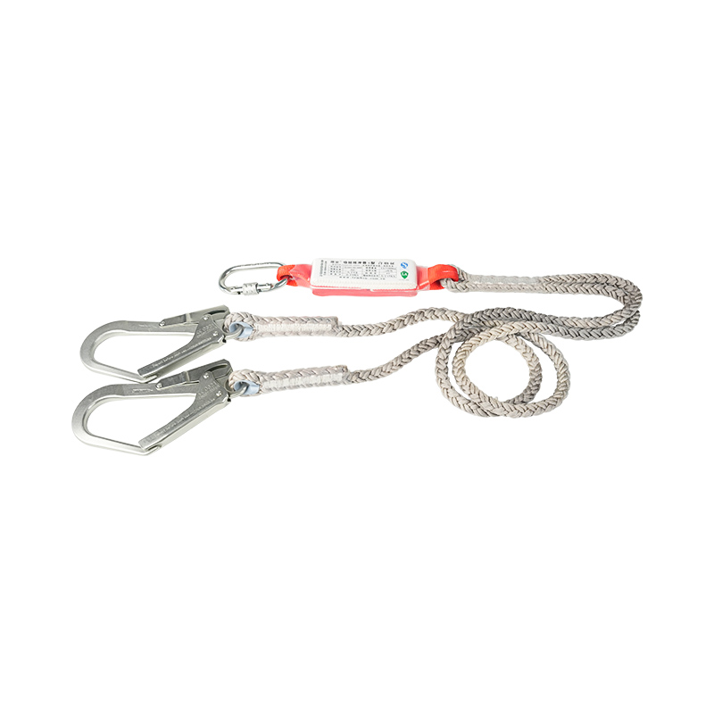
For teams who mainly work from a single anchor at a time, a single-leg rope configuration can be easier to manage. As one example, our LS04 specifications list polyamide rope construction and a static tensile strength of at least 22 kN, with selectable rope lengths for certain configurations. This kind of product is typically used with an energy absorber when in fall arrest mode, so clearance planning remains essential.
If your travel path, connectors, or branding requirements vary by project or market, we also support customization; you can start from our Custom Safety Lanyard page to define length ranges, connector types, and compliance targets.
When customers ask us for a “standard” rooftop or steel lanyard, we respond with a checklist—because the wrong assumption is usually made before the order is placed. Use the checklist below to align purchasing with your actual travel plan.
For training-friendly connection practices, you may also reference our step-by-step harness and lanyard use article. If you want to review the full range of lanyard categories and configurations we supply, return to our safety lanyard product page.
Final note: lanyard length decisions should never be made in isolation. The correct solution is the one that matches your roof or steel travel plan, fits your clearance, and keeps workers connected without improvisation.

San Ye Road, Si Xiang Sub-district, Hai Ling District, Tai Zhou City, Jiang Su Province, China

+86 151-5262-8620
Copyright @ Taizhou KA Protection Products Co., Ltd. All Rights Reserved

 English
 Español
 عربى
عربى
